 English
 España
 عربي
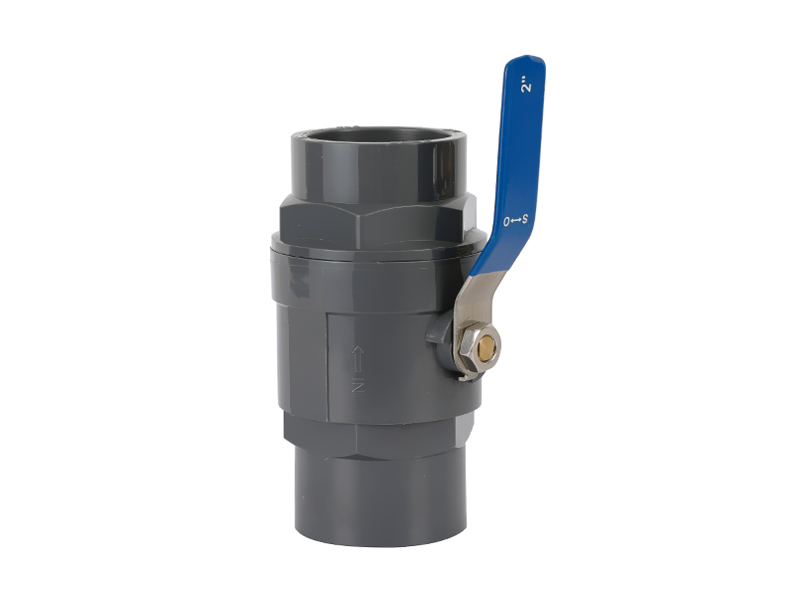
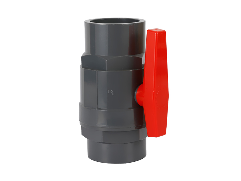
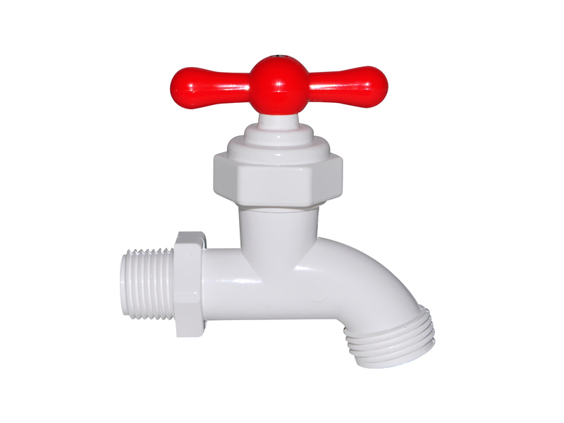
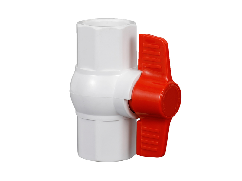
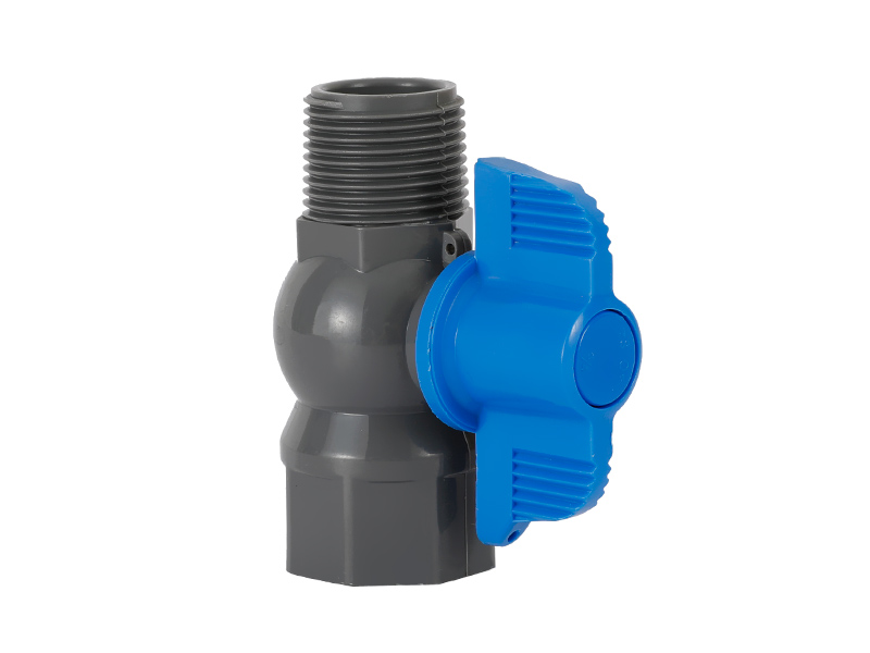
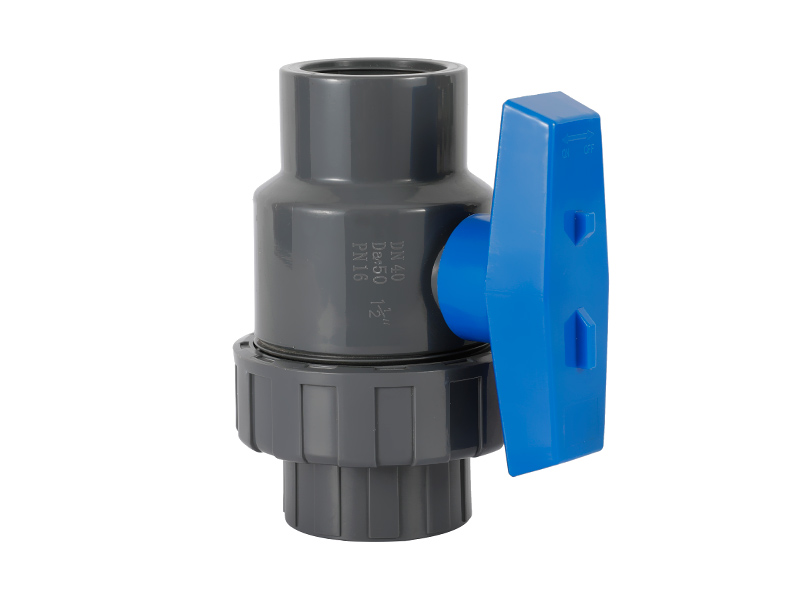
عربيHow does the male ball valve design enable smooth and effortless on/off operation?
The male ball valve design is a key characteristic...
MORE >>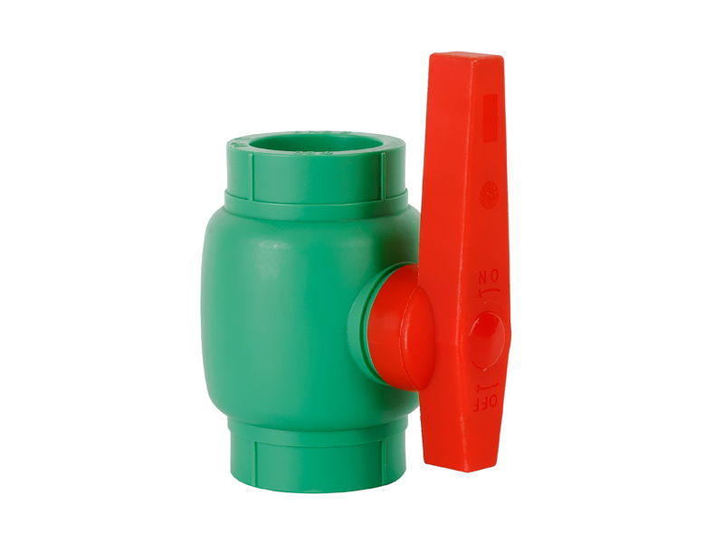
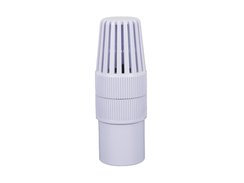
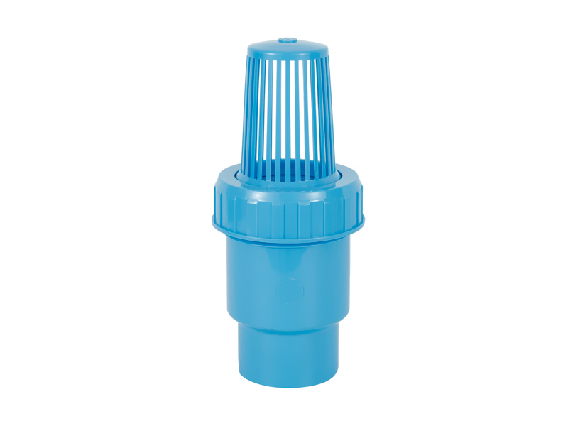
It can Check Valve increase and adjust the frequency va […]
It can Check Valve increase and adjust the frequency value that matches the overall target slew rate to obtain the frequency value of the proportional solenoid valve PWM driver data signal under different temperature standards. High temperature and large frequency value reduce the gear oil temperature The change of gear oil viscosity caused by different heights harms the insufficient response characteristics of the solenoid valve. The inventor has tested the proportional solenoid valve driver method based on PWM, and used the proportional solenoid valve equipped with the KPM-K3V motor control pump as the experimental target motor control pump. The oscillation frequency of the proportional solenoid valve equipped with the motor control pump is 80 Hz. Using the Bode diagram of the second-order low-pass filter, it is known that the mechanical structure of the solenoid valve will suppress the fluctuation of the current with a frequency exceeding 80 Hz. And the higher the frequency of the current, the stronger the suppression effect of the second-order oscillation system software of the mechanical equipment.
The circuit system of the solenoid valve is equivalent to a first-order low-pass filter. From its steady-state value, the cut-off frequency of the circuit system is . Compared with the mechanical structure, its suppression effect on the PWM single pulse fluctuation data signal is relatively small. Therefore, the filter characteristics of the mechanical structure can be used to filter the PWM signal to obtain the required stable working voltage, but in addition, the small amplitude current fluctuations required by the valve core itself need to be preserved. Therefore, it is possible to obtain the proportional solenoid valve variable frequency PWM driver under different temperature standards. When the current is larger that is, the slew rate is larger, such as and the least (that is, the slew rate is the least, such as 0MA To achieve a PWM with a stable secondary working pressure, the frequency value is low, and when the current is in a negative correlation of 324mA that is, the slew rate is a positive middle value, such as 50%), a higher frequency must be selected. The results of basic theoretical analysis are consistent. In addition, when the temperature is higher than 36°C, PWM with stable secondary working pressure should be achieved, and the frequency value should be higher.
Proportional solenoid valve PWM boost frequency In this example, different PWM frequencies are selected according to the slew rate required for proportional solenoid valve operation. Actually, the slew rate on both sides should be the lower PWM frequency, and the slew rate in the middle Select a higher frequency to achieve a stable output working pressure of the proportional solenoid valve, avoid valve core sticking and reduce power consumption. The system operation and maintenance example is shown in the implementation example of this product. The structure block diagram of the proportional solenoid valve driver system software based on PWM is shown in the explanation of the matching implementation example. This implementation example is applicable. A PWM-based proportional solenoid valve driver system software includes: Correspondence settings The fixed module is used to pre-set the corresponding relationship between the slew rate and the frequency value. The regularity of the frequency value in the corresponding relationship is that the frequency value matching the slew rate in the middle exceeds the frequency value matching the slew rate on both sides.
The clear module is used to clarify the frequency value that matches the overall target slew rate according to the corresponding relationship; the driver data signal is converted into a module, which is used to convert the overall target slew rate and the matching frequency value into a PWM driver data signal; the driver Module to use the PWM driver data signal to drive the proportional solenoid valve. Practically, the frequency clear module can include: a measurement sub-module not shown in the figure, which is used to carry out linear interpolation measurement according to the corresponding relationship to obtain other frequency values that match the slew rate; the clear sub-module not shown in the figure , which is used to determine the frequency value that matches the overall target slew rate based on the result of linear interpolation measurement. The corresponding relationship setting module can include a storage sub-module (not shown in the figure for pre-setting the matching frequency values when the slew rate is 10%, 50%, and 90%, where 50% of the slew rate is In the middle of the slew rate, the frequency value that matches the slew rate is larger. The slew rate is 10% and 90%, respectively, the minimum slew rate and the larger slew rate. The slew rate is 10% and/or 90% match has the least frequency value.
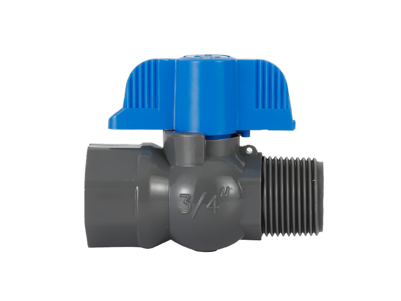
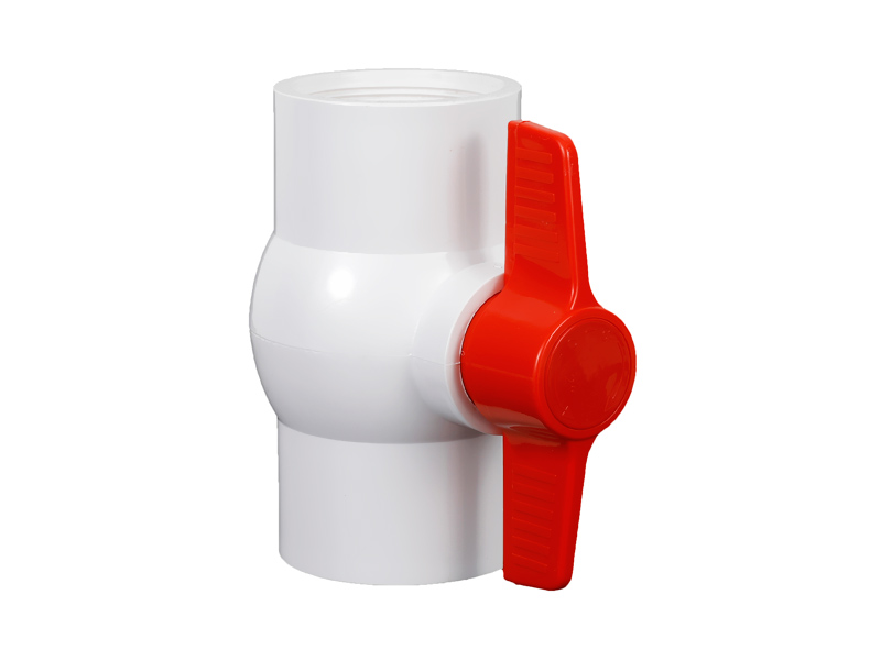
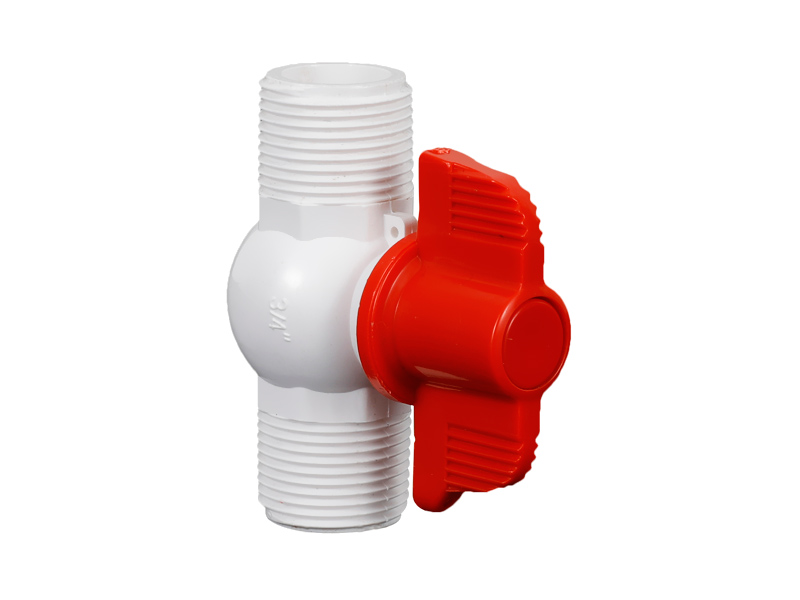
The male ball valve design is a key characteristic...
MORE >>
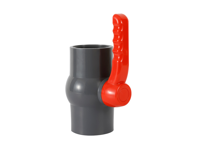
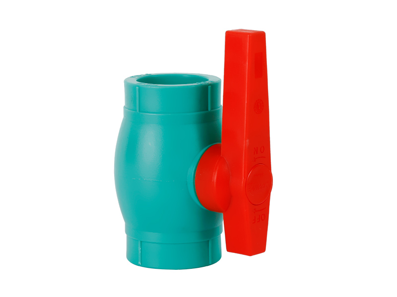
In today's modern world, efficient and reliable wa...
MORE >>
Copyright ©All rights reserved:Zhejiang Xier Plastic Valve Lead Co.,LTD. PVC Ball Valves Manufacturers Technical support: HWAQ  浙公网安备 33060402001174号